How to Remove Bright Spots and Dead Pixels in Video or Images
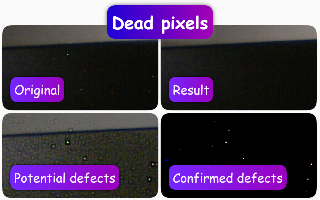
Problem
While a camera is operating, pixels can light up and disappear live. Heating and changes in ISO alter the physical operating characteristics of the semiconductor sensor, causing defects to appear in real time.
In Short
How to fix it: find the effect Dynamic dead pixel correction and select Light in the Page context extension.
Result: bright spots will stop glowing.
There is also a Full mode, but it is suitable for powerful GPUs, or for weaker ones if you apply the effect to a still image rather than video.
The source and type do not matter. What matters is that the frame is not scaled.
How People Usually Solve This
- Intuitive simple solution. Such pixels can easily be made less noticeable by reducing the camera resolution. The algorithm averages neighboring pixels, and you get a result where almost 100% of pixels are distorted for the sake of a few very noticeable pixels.
- Professional complex solution. Put a cap on the camera, warm it up to operating temperature, etc. Then the algorithm creates a permanent mask for correction.
Problems with Common Approaches
- It does not solve the problem when defective pixels appear right now. Every time people do this, they have already damaged something before they start fixing it.
- A mask removes information about pixels for a long time, even though those pixels may work fine at another ISO or a lower temperature. You can remap defective pixels in hot weather, blocking pixels that work normally at cold temperatures.
- Such functions are not implemented for all cameras.
- You need to know how to do all of this.
- If your camera has low resolution, you will noticeably lose quality when downscaling.
- Most correction algorithms work as a black box: the user can only turn them on or off, without knowing how many useful details in the frame were destroyed.
The defect is dynamic, so an adaptive local solution is needed, not a static mask and not global averaging.
Remapping is suitable for stable defects on a specific camera, but dynamic correction is needed because it works when defects appear/disappear depending on conditions.
Solution via the Page context Extension
You can select the Light or Full preset, which work in real time and adapt to each frame. The decision is made based on the current frame, not on a saved mask. No knowledge is required to run the preset, and fine-tuning is available for those who need it. For professional correction, there are many parameters for adjustment with suitable visualization of the different algorithm stages. If a pixel has just become defective or has just stopped being defective, the algorithm adapts instantly. When you switch to another camera, the algorithm requires no special actions; it works with any image, even video and pictures from the internet. It does not spoil all pixels as downscaling does; it changes only detected defective pixels on the fly. This highlights the core functions of the Page context extension, providing seamless, real-time adaptive correction directly in your browser environment.
Capabilities
You can limit the algorithm’s operation by specifying which camera it should be applied to, so as not to affect high-resolution cameras due to additional GPU load. You can specify a text template for the camera name to apply it to the desired camera.
Presets
- Light — cheaper on GPU, pointwise per-channel correction, but the patch may stand out and does not cover a blurred defect.
- Full — more expensive on GPU, expanded patch with edge blending, higher quality.
Stages
Stage Final result
How it works
The algorithm creates patches and replaces defects with them. In the final stage, you can adjust the degree of blending of the patches with the original image. The algorithm uses 2 types of patches: precise per-channel and expanded with edge blending.
The precise per-channel patch works on the channel where the deviation was found, but this may not be enough for 2 reasons:
- The replacement is made with a patch that may stand out.
- The defect may be blurred across several pixels.
To solve these problems, there is an expanded patch that blends with the original, gradually fading toward the edges. But the expanded patch cannot work normally per-channel, because the channels of the original and the expanded patch are mismatched. Using only the defective channel in the expanded patch would lead to color distortions, so the expanded patch affects all color channels.
Parameter adjustment
- Precise mask strength. Adjusts the degree of blending of the precise per-channel per-pixel patch with the original.
- Expanded mask strength. Adjusts the degree of blending with the expanded patch.
Stage Edge blending
How it works
At the edge-blending stage of the expanded patch, the patch size and the blending of its edges with the original are configured.
To calculate the base for the patch, the detected defective pixel is enlarged in size across all channels, even if the defect is only on one channel. The resulting expanded area is blended with the original.
Display
An additional view shows a black-and-white expanded map of detected defects. You can see in real time how its shape changes when its settings are adjusted.
Parameter adjustment
- Blend size. Radius of the expansion zone around the defective pixel. The smaller this size, the smaller the patch halo will be. The larger the size value, the larger the defect zone around the defective pixel itself will be corrected. You should start increasing the size while watching how the damaged zone around its central point disappears. Do not increase the size unnecessarily, otherwise useless artifacts from the algorithm will appear in the form of blurred areas.
- Blend blur ratio. Blur radius of the blend zone, expressed as a coefficient relative to the blend size.
Stage Replacement material
A blurred original image is used to replace the area of defective pixels.
Skin blur radius. Sets the blur radius for the blurred original image. The larger this radius, the less the patch on the defective pixel resembles the area of the defective pixel and its immediate surroundings, but the patch may deviate too much from neighboring pixels — this is useful when an entire group of pixels is defective. With a small radius value, the patch can match neighboring pixels more precisely, but the defect itself may be hidden worse — this is useful when the defect is small in area.
Stage Confirmed defects
How it works
At this stage, the algorithm’s response to the geometric model of defective pixels is configured. Here you set how the adaptive brightness of a defective pixel relates to the maximum of that brightness among surrounding pixels.
The brightness ratio of pixels can involve both large and small absolute values, but small absolute differences are barely noticeable to the eye. Therefore, the maximum adaptive increase in absolute brightness values for the algorithm is limited here.
Display
An additional view shows a map of detected defects, which changes in real time, and the user sees the boundary between digital sensor noise and real defects.
Parameter adjustment
- Maximum gain (Db). Limits sensitivity in absolute brightness value. Shows the limit to which brightness can be increased to detect defective pixels. That is, the larger the value, the less bright defects can be detected. The algorithm itself has artifacts, so in order not to make things worse than they were, defective pixels that are poorly visible probably should not be improved; that is, you should carefully increase the parameter value so that the negative effect does not outweigh the positive one. If you increase the value too much, you can reach a level where you simply start correcting noise, and you will add many artifacts. But if you do not increase it enough, some defective pixels will not be detected at all.
- Peak ratio. Sets the minimum ratio of the adaptive brightness of the detected pixel to the maximum of that brightness among neighboring pixels.
Stage Potential defects
How it works
At this stage, geometric parameters for identifying defective pixels are configured. Here you see a pattern that helps detect defective pixels.
As a rule, you see dark frames around bright pixels.
Display
The additional view shows how the algorithm recognizes defects internally. Dark frames show how the algorithm’s settings geometrically fit defect detection, and the brightness of the defects themselves is adaptively amplified.
Parameter adjustment
- Defect radius. Here you define the radius within which the algorithm excludes data for calculating the reference brightness value. The higher the parameter value, the larger the recognition zone radius. Usually this value should be from 1 to 3 pixels. With a small radius value, the algorithm poorly recognizes large defective areas, but large values will lead to nearby defects not being detected. When tuning, the dark frames should cover the entire defect, but not neighboring ones.
- Reference border thickness ratio. This is the border thickness as a fraction of the defect radius. The border is the reference value for determining an anomaly. The wider the border, the fewer pixels can be detected.
Limitations
The algorithm works well only on a raw frame without scaling, since it needs the original pixel because of its brightness. If you change the scale, there is almost no point in using the algorithm; the algorithm will try to remove much larger objects than pixels, and the information for detecting defects becomes difficult to access.